
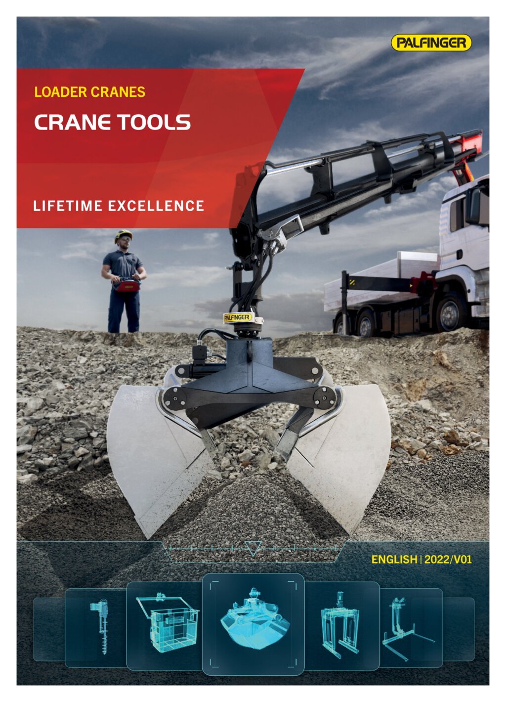
Palfinger Loader Cranes
Notice: Undefined variable: out in /mnt/wordpress_data/fo.kj/wp-content/themes/twentyseventeen-child/template_palfinger.php on line 281
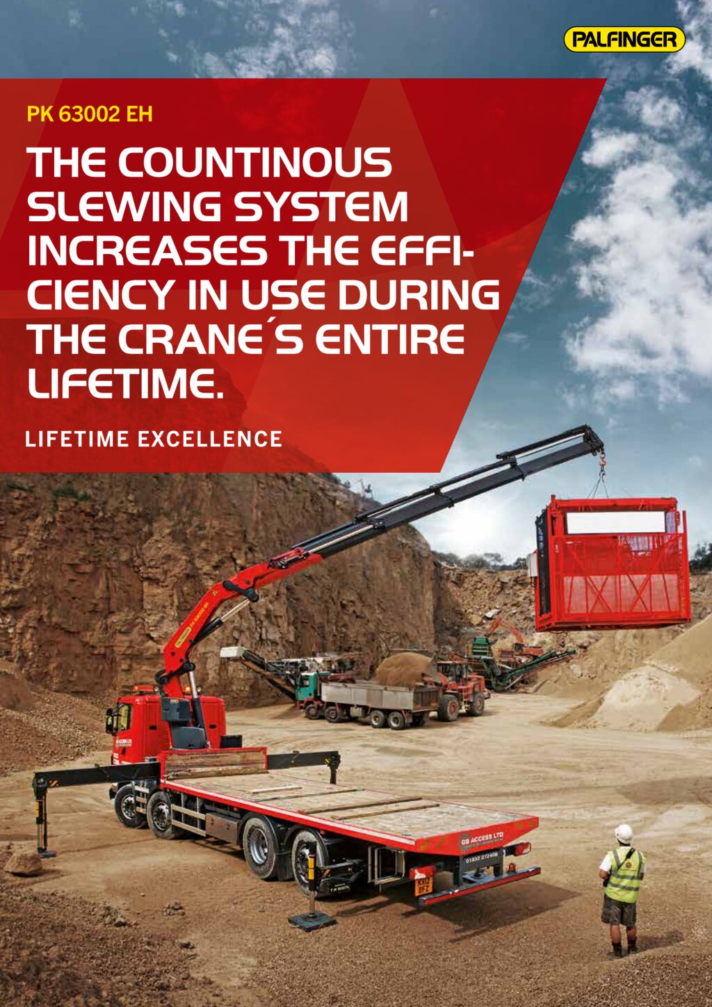
PK 63002 EH High Performance
The continuous slewing system increases the efficiency in use during the crane's entire lifetime.
-
More effcient and faster due to continuous slewing system
-
More lifting power due to E-HPLS
-
Practical and attractive due to Functional Design
-
High value retention thanks to coating technology
Brochures
PK 63002 EH
| Max. lifting moment | 59.4 |
| Max. lifting capacity | 22000 |
| Max. hydraulic outreach | 20.4 |
| Max. manual outreach | 25.1 |
| Max. outreach (with fly jip) | 30.4 |
| Slewing angle | ∞ |
| Slewing torque with 1 gear | 4.5 |
| Slewing torque with 2 gears | 7.0 |
| Stabilizer spread (std) | 8.6 m |
| Max. operating pressure | 350 |
| Pump capacity | 80 - 100 l/min |
| Dead weight (std.) | 5040 |
Cranes shown in the leaflet are partially optional equipped and do not always correspond to the standard version.
Country-specific regulations must be observed. Dimensions may vary. Subject to technical changes, errors and translation mistakes.
Country-specific regulations must be observed. Dimensions may vary. Subject to technical changes, errors and translation mistakes.
Lifting moment | Outreach | Slewing angle | Slewing torque (mt) | Pressure | Pump capacity (l/min) | Crane Weight | Crane Height | Crane Width | Installation Width | Max stroke lenght | Max lifting capacity | Load vertical | |
|---|---|---|---|---|---|---|---|---|---|---|---|---|---|
| A | 57.2 mt | 7.6 m | ∞ | 4.5 / 7.0 | 35.0 Mpa | 80-100 | 5040 kg | 2450 mm | 2550 mm | 1555 mm | 7433.45 mm | 21800 kg | 7900 kg |
| B | 56.2 mt | 9.5 m | ∞ | 4.5 / 7.0 | 35.0 Mpa | 80-100 | 5384 kg | 2450 mm | 2550 mm | 1555 mm | 9360.45 mm | 21500 kg | 6000 kg |
| C | 55.4 mt | 11.5 m | ∞ | 4.5 / 7.0 | 35.0 Mpa | 80-100 | 5676 kg | 2450 mm | 2550 mm | 1555 mm | 11365.45 mm | 21300 kg | 4750 kg |
| D | 54.5 mt | 13.7 m | ∞ | 7.0 | 35.0 Mpa | 80-100 | 6096 kg | 2450 mm | 2550 mm | 1555 mm | 13575.45 mm | 20500 kg | 3700 kg |
| E | 53.6 mt | 15.9 m | ∞ | 7.0 | 35.0 Mpa | 80-100 | 6404 kg | 2450 mm | 2550 mm | 1580 mm | 15708.45 mm | 20000 kg | 2950 kg |
| F | 53.0 mt | 18.1 m | ∞ | 7.0 | 35.0 Mpa | 80-100 | 6630 kg | 2450 mm | 2550 mm | 1685 mm | 17958.45 mm | 19100 kg | 2350 kg |
| G | 52.6 mt | 20.4 m | ∞ | 7.0 | 35.0 Mpa | 80-100 | 6804 kg | 2450 mm | 2550 mm | 1685 mm | 20268.45 mm | 18400 kg | 1940 kg |
The outreaches stated are with a boom angle of 20° and are therefore not the maximum. When using mechanical boom extensions, the loads shown on the charts need to be reduced by the weight of these extensions.